1999 Ford Ranger EV
I own a 1999 and a 2001 Ford Ranger EV. In August 2008 I purchased 200 LFP cells from China Hi-Power. I also purchased two 5 amp chargers from CHP in order to comply with the language of the 2-year warranty. At the time, the 5 amp model was the only single phase charger CHP made. Both vehicles have now been converted from their original lead-acid configuration to accommodate LiFEPO4 cells.
NOTE: The pack for the 1999 was replaced under warranty August 2010. Scroll down to view information about installing the second generation cells.
- I do not recommend that anyone else should do their own conversions.
- I DO NOT claim that my techniques are correct or safe.
IT IS IMPORTANT TO STAY ALERT AND CAREFULLY OBSERVE ALL HIGH VOLTAGE CAUTIONS/WARNINGS
IN THE MANUAL
It is also critically important for anyone who attempts to do their own conversion to realistically appreciate their own abilities and limitations. In other words, one must always recognize what they don't know.
NOTE: When I compared Connector Face Diagrams to the Traction Battery Diagrams,
I discovered multiple errors in wire number designations as well as a few color errors.
I corrected these errors on the new diagrams listed below
Wiring diagram 16-12
Wiring diagram 16-13
Wiring diagram 16-14
Wiring diagram 16-15
Wiring diagram 16-16
HIGH VOLTAGE
150-73, C1865
150-75, C1866
LOW VOLTAGE
150-111, C1986
150-112, C1987
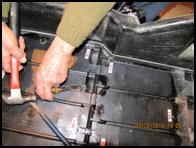
In order to change the location of the pins and wires I used an extractor tool. I also removed all unused wires/pins intact so they could be used in other locations.
| |

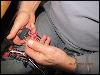
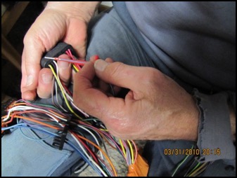
I reused original resistors and used 16g wire rated at 600v to lengthen wires between the BCM and the plug where required. I then wrapped the wires with orange PVC tape. I used crimp connectors and shrink tube to connect the added lengths. I could have used solder and shrink tube.
To connect the battery sense wires for the BCM, I used either ring terminals to the positive post or crimp connectors & shrink tubing to join the sense wires to battery cables where applicable. Refer to wiring diagrams 16-12 through 16-16.
LETTER DESIGNATION | BATTERY MODULE |
M | 21, 19 |
| P | 23 |
| E | 22 |
| F | 17, 18, 20 |
| N | 24 |
| L | 16 |
| K | 14 |
| J | 12, 15 |
| S | NOT USED |
| T | NOT USED |
| H | 10, 13 |
| C | 5 |
| D | 6 |
| A | 1, 3 |
| V | NOT USED |
| R | LOW (0) |
| U | NOT USED |
| W | HIGH (25) |
| B | 2, 4 |
| G | 7, 8, 9, 11 |
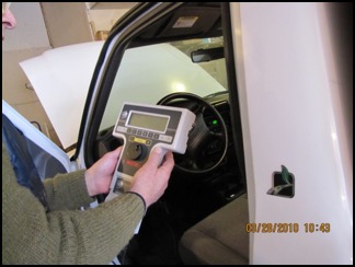
In order to convert my lead acid Ranger EV to LiFEPO4, I first configured the vehicle to NiMH. I, and most people who have done successful conversions, consider the NiMH algorithm to be the most compatible with LFP cells.
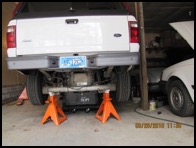
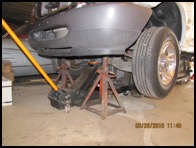
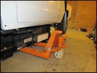
The SLA truck must be in running condition in order to flash the BCM because the program must be able to see all the components to test function. This does not mean the motor is actually running with its wheels turning, it simply means the truck is truly drivable. Further, I learned the hard way that it is important to have the vehicle positioned where it needs to be before the process is started.…once it is up on jack stands, the truck can’t be moved and it has to be close enough to a 220VAC power outlet in order to connect the charger to test the conversion before reinstalling the battery tray. An NGS tester and the flash program (BCM 08/31/99 XL5F-10B687-AH v0 for NiMH), are required to change from a lead acid to a NiMH configuration. I connected the NGS Tester, inserted the card, and followed the instructions on the display.
BATTERIES
The LiFEPO4 pack consists of one hundred (100) 100ah cells.
I began preparing the cells by arbitrarily identifying each cell with a number from 1 to 100 using a black permanent marker. Cell #1 is high (332V), and cell #100 is low. The negative terminal of cell #100 is ground and the positive terminal is 3.34V. Battery modules are comprised of cell numbers as shown in Module Chart. In addition, I also labeled the first cell (most positive cell) of each battery module with its respective module number using a red marker, also shown on the Module Chart. This procedure created a battery pack that appears to be twenty-five (25) 12V batteries.
LFePO4 cells to NIMH configuration Chart
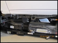
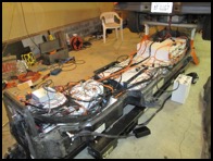
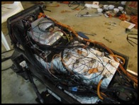
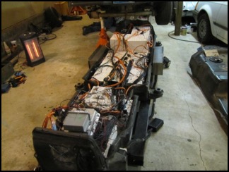
I placed the cells in the tray to see how and where they would fit prior to banding.
Cells 5-34 and 57-86 are placed on their narrow sides with terminals facing outward. Cells 87-100 are placed on top of 86-71. Cells 1-4 are on top of 5-34.
Remainder of cells are upright to front side of ventilation fan.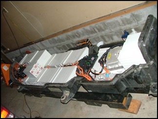
| The next step was to band the modules together. I used ½” poly strapping, which is available from Northern Tool Equipment. The strapping was $60.00 for a 4500 ft roll, the tensioner was $35.00, the sealer was $33.00, and 500 seals were $20.00. |
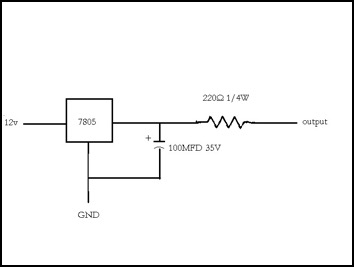
Schematic for Sense Line and Speed Control Line
As of May 2010 the 1999, with its LiFEPO4 pack, had been driven about 1800 miles. Because of the severe winters and road salt, I do not drive the EVs between October 31 and April 15.
The maximum temperature observed during either charging or discharging was 32C and that was observed on only one occasion. Normally the temp is around 20C. It should be pointed out that the ambient temperature where I live rarely exceeds 85F. For me, in this location, there is no heat problem with the LFP cells. I am using the original vent fan with a speed control modification and added a $20 substitute fan for the flow-through fan with a modified sensor for FTF feedback.
I started out with a range of about 50 miles. My sales contact at HiPower had assured me I would get +/- 75 miles so I hoped the range would increase after the "break-in" period. Unfortunately, the range began to diminish instead. CHP had required me to use their 5 amp charger in order to maintain the warranty, and I suspected it was undercharging the cells. In addition, both chargers failed within a month of use. HP did provide a wiring diagram and parts list so I could repair the chargers, they still did not provide adequate performance. After several communications, CHP finally agreed to allow me to use the Ford on-board charger and keep the warranty in force. With the on-board charger, the range began to stabilize and I hoped that it would improve, but that expectation was overly optimistic. When we added the MiniBMS by CleanPowerAuto, we identified why we were having problems. Multiple cells were exhibiting voltage sag--some within just a few miles of completing a full charge. The voltage sag was more pronounced when the pack was partially discharged and was particularly aggravated by driving more than 50 miles or on grades over 5%. Over the summer of 2010, the range dropped more and more until it was down to +/- 20 miles. The poor range may have been caused by initially using the 5amp charger; there may have been inconsistent or less than ideal cell technology; or the cells were simply not strong enough to power the heavy Ranger on the hilly terrain in my area without voltage sag.
The 1999 was a long struggle but, with invaluable assistance from Chuck Malitz of Pacific Rim Far East, CHP finally replaced the whole pack for the 1999 Ranger in August 2010. CHP sent me 100 of their second generation HP-IFP-W-100ah cells (163mm x 62mm x 282mm 3950 GM), which are larger than the original (160mm x 50mm x 282mm, 3500 GM) and have a 3C discharge rating. When the pack arrived, I could hardly believe my eyes. These new style cell had huge, non-industry standard 19mm posts. They did, however, have special heavy-duty straps to fit those posts plus high torque nuts. These features initially presented as a disadvantage since no connection hardware for the high voltage battery cables is readily available. However, after resolving those issues, the same characteristics have become an advantage. The oversize posts not only act as a heat sink, but they also more easily allow for single cable connections, especially for high voltage, which greatly reduces the chance to develop loose connections. I drilled and tapped holes in the middle of the straps to connect BMS and BCM wires so there are fewer connections on the posts.
To compare specifications for the three generations of HiPower cells, see following documents:
First Generation Second Generation Third Generation
Before I describe the installation of the replacement second generation cells, I will first report on the MiniBMS because this equipment was critical in defining the poor performance issues of the original HP LFP packs.
MiniBMS by CleanPowerAuto
The BMS is available in Individual and Centralized versions. The Individual has boards mounted on each cell and a control panel, mounted in the cab or under the hood, which has a warning buzzer to indicate high or low voltage. There is no LED display visible to the driver. The Centralized version has wires from each cell that connect to a central control board, which is mounted in the cab, and has a warning buzzer plus two LEDs/cell that monitor each cell. Since I already had balancing wires in place from the HP 5amp charger, I used those wires and their aviation plug connectors to install the MiniBMS. This configuration not only worked well for the BMS, but also provided easy access for single-cell charging.
Cell to BMS Wiring.pdf
In the Cell to BMS Wiring diagram:
THE 101 BALANCING WIRES ARE CONNECTED THROUGH FIVE CABLES
WIRES/CELL # 25-1
CABLE 5
WIRE/CELL # 49-26
CABLE 4
WIRE/CELL # 69-50
CABLE 3
WIRE/CELL # 86-70
CABLE 2
WIRE/CELL #101-87
CABLE 1
Red numbers represent Battery Module numbers
AVIATION PLUGS
CONNECTING BALANCING WIRES FROM CELLS TO BMS WIRES
Procedure I use for disconnecting and reconnecting Centralized BMS
when servicing the pack:
- Disconnect from high voltage to low voltage—cables 5, 4, 3, 2, 1 in order.
- Connect from low voltage to high voltage—cables 1, 2, 3, 4, 5in order.
- Have assistant confirm successful disconnect/reconnect by observing LED display
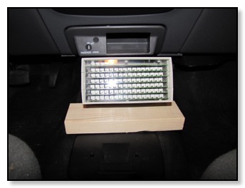
MiniBMS DISPLAY, MOUNTED IN CAB
During discharge, the green LEDs monitor voltage
The green LEDs turn off any time cell voltage is below 2.6
The low voltage reading is temperature compensated
to avoid false alarms during low ambient temperatures
See MiniBMS Manual for more detailed information at www.cleanpowerauto.com
A co-pilot must be available to identify cell numbers
During re-charge, a green LED indicates voltage less than 3.65v and a red indicates voltage over 3.55.
When cells reach 3.55v, equalization begins and is indicated by red LEDs. The green LED turns off when cells exceed 3.65v.
Equalization take place as long as the voltage is above 3.55.
Once the first cell exceeds 3.65v, the BMS turns off the charger.
Complete instructions can be downloaded from
www.cleanpowerauto.com
CleanPowerAuto is able to configure the upper
voltage set point at either 3.65 or 3.85. The set
point is not adjustable in the field.
The MiniBMS Centralized version does have some disadvantages. It is harder to install because there are more wires and connections. This means there is more expense to purchase the hardware and it is more susceptible to wiring errors, which can easily short the board causing damage which may be repairable or permanent. It also requires a housing for the display unit, which is not supplied by the manufacturer. Because of the more complicated installation, repairs are more difficult.
Nonetheless, I prefer the Centralized version. With the warning buzzer and the LED display in the cab, my passenger/assistant can easily identify the quantity and location of any cells which exhibit voltage sag. The sag can also be linked to the amperage load that caused the sag. One can also identify any cells that go over-voltage during regeneration. This is important because this condition can be a sign of impending cell failure. These parameters are easily identified in real time and under load.
A new pack may have a few cells that do not achieve full charge. However, with subsequent charge/discharge cycles, more cells reach full charge through the equalizing process. During charging, one can see which cells are entering the equalizing phase and which cell first reaches the set voltage to turn off charger. Being able to see the progress toward a fully balanced pack is helpful when using single cell low amperage charge/discharge to fine tune the pack balance without dropping the pack. See www.cleanpowerauto.com for discussion of initial pack balancing, which I found very helpful.
The MiniBMS Individualized version is easier and less costly to install plus there is less chance for wiring errors. The warning buzzer can be installed under the hood or in the cab. The warning buzzer indicates voltage sag under load and over-voltage during regenerative charging while driving. However, you cannot identify the quantity and location of cells that are triggering the warnings. If one did not have some kind of third party equipment to monitor each cell, one would have to drop the pack and use a chassis dynamometer to identify the problem cells under load
The left side of diagram is the back and the right side is the front. The black numbers represent cells and the red numbers are battery modules as seen by the BCM. All cells to the rear of the fan are oriented on their narrow side with battery posts toward the outside wall of the container. Cells 100 through 89 are on top of 88 through 77. Cells 1 through 4 are positioned with their posts oriented toward the rear of the container. Cells in the SS auxiliary containers are laying on their narrow edges, posts face to face with insulation and spacers in between. All cells to the front of the fan are mounted in the upright position except for numbers 34, 35, 58, & 59 which are on their narrow edges with posts oriented toward the rear. Cables attached to numbers 72-, 69+, 21+, and 24- are secured with 8 mm aluminum bolts. It was necessary to drill and tap the posts on these four cells to attach the cables.
INSTALLING HP-IFP-W-100AH SECOND GENERATION CELLS
The left side of diagram is the back and the right side is the front. The black numbers represent cells and the red numbers are battery modules as seen by the BCM. All cells to the rear of the fan are oriented on their narrow side with battery posts toward the outside wall of the container. Cells 100 through 89 are on top of 88 through 77. Cells 1 through 4 are positioned with their posts oriented toward the rear of the container. Cells in the SS auxiliary containers are laying on their narrow edges, posts face to face with insulation and spacers in between. All cells to the front of the fan are mounted in the upright position except for numbers 34, 35, 58, & 59 which are on their narrow edges with posts oriented toward the rear. Cables attached to numbers 72-, 69+, 21+, and 24- are secured with 8 mm aluminum bolts. It was necessary to drill and tap the posts on these four cells to attach the cables.
I applied dielectric grease to all threaded fittings, washers, & nuts and then proceeded to attach the hardware. I have two 30mm wrenches—a 3/4" drive socket, which I used with an adapter to a 1/2" ratchet wrench (about 12" long) and a heavy duty box/open combo which is approximately 18" long. After arranging the cells, attaching straps and wiring, I tightened each nut so they are very snug with a wrench appropriate for the cell position.
As an old “battery man”, I do not lay batteries on the wide edge because I am concerned about stressing the plate to post connections. In order to install the cells that lay on their narrow edges, I first assembled them into groups of four or six with strapping bands. I used the socket wrench to tighten all post straps while cells were upright and I made sure that the post straps that connect the groups together once they are laid on their sides and lowered into the container, were upper straps that could be reached with the combo wrench. I insulated nearly the full length of the wrench with electrical tape so I could reach in alongside the container wall without shorting any of the other connections. I used some old seatbelt nylon strap to make "carriers" for the inner aspect of the cells that are horizontal and used pull straps wrapped around the metal post straps so that I could hold each cell group in a horizontal position to lower it into the tray. Since I installed the centralized BMS, all of the straps were prepared with the BMS wiring at the time of installation. Once the groups were lowered into position, I could make the final connections with the insulated combo wrench. As you can see from the diagram, I was able to install 31 cells per side.
Straps for standard and 19 mm posts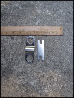
19mm strap with hole drilled & tapped to attach BCM & BMS wires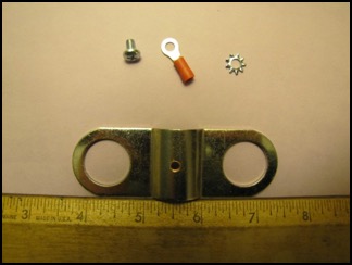
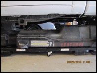
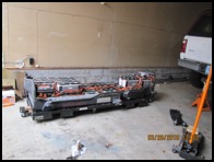
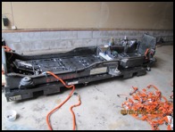
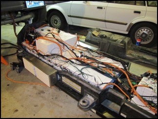
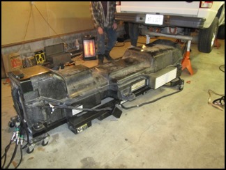
Here are several views of the second generation cells as they are positioned in the battery container.
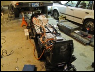
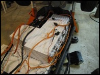
Since I feel it is imperative to have all cells permanently installed and protected, I had to devise a way to safely install the 8 cells that would not fit in the OEM tray. I had two stainless steel auxiliary containers fabricated. These containers are designed to safely hold the cells while preventing wiring shorts. They are permanently attached with special epoxy to the main tray so that connections to the pack are protected. Although temperature has never been a problem in my area, the stainless steel does act as a heat sink. The temperature can be monitored with a simple handheld IR thermometer or one could install two thermistors and a thermometer to read the temperatures of both containers.
In addition to the SS container assemblies including epoxy and mounting hardware, I also fabricated the following:
Three diagonal straps with 19mm holes
6 horizontal straps with 19 mm holes
2 “U” straps with 19 mm holes
22 19 mm cable connectors for high voltage cables
I installed an extra 1/4" gasket between the top cover and the bottom tray. This was the only additional clearance to accommodate the 92 second generation cells. The pack installed as usual and the auxiliary containers fit as planned.


GEN 2 PERFORMANCE REPORTS
Fall 2010
Winter snows arrived a little late this year so I was able to put about 500 miles on the pack before PennDot started salting the roads. The temperatures were, however, 20-35 degrees. The BMS never indicated voltage sag, even on a 9% grade. I have not pushed the range but after 40-50 mile trips I still had 50% SOC remaining. My wife drove several of the trips with the same results. This is important because she drove partly on the interstate at 55-60 mph with lights, wipers, & heater running.
1999 Ranger EV in winter storage as of December 2, 2010
Spring 2011
After a cold winter, spring 2011 finally arrived in mid-April and I put the 1999 Ranger EV back in service. We made three or four 40-50 mile range trips very easily with CSOC showing more than 50%. The pack seemed to be performing the same as it did last fall before the winter storage. In late April I needed to get to a destination that was 50+ miles away. I planned to recharge at the destination because I was going to be there for several hours. The day was rainy with an ambient temperature of 40 F but the trip out was uneventful and part of it was at 60mph. When I arrived, CSOC showed 55% remaining and the odometer read 52 miles and AHC read 94.5. I started charging and went about my business. When I later checked on the truck, I was unpleasantly surprised to see that the charger was not working and I saw Op code 99 on the NGS Tester. I was unable to get the charger working. I realized that it had charged for only a moment or so because there were no changes in the gauges. I was worried that water intrusion had somehow caused damage and I was not all sure if the problem was in the charging station or the on-board charger. Having no other choice, I notified Carol that she may have to come to my rescue and then started the return trip home. I drove this leg much more conservatively than the first. I limited speed to 45 mph, except when I was in traffic that required 55 mph for safety reasons. I had 92 miles on the trip odometer, when the Centralized BMS gave a low voltage signal on one cell. That cell was battery module #12/cell #2. Cell #55 on above charts. The distance-to-empty gauge read 20+ miles and the CSOC gauge read just under 30%. The SOC on the NGS Tester showed 77%. Further, the Ranger diagnostics had not shown any limiting signal on either the DTE gauge or the low-fuel telltale. Nonetheless, I did not want to risk damaging the cell that gave the low voltage signal, so Carol came to tow me home. Once in the garage, I checked the voltage of each cell using the BMS wires, and I was unable to determine which cell had given the low voltage warning. If I had not seen the LED on the centralized BMS, I would not have been able to identify the cell. I then plugged in another charging station. Thankfully, it worked so the problem was in the first charging station and not the vehicle. I fully recharged and, to my surprise, the AHC had increased from 94.5 to 95.8. The following day I made a 60 mile trip quite easily. Although I have not yet tried, I suspect, I could get the round trip of 104 miles if I drove conservatively the whole way, and I might have made it the first time if I had ignored the BMS.
Since then we have been consistently making 60-70 mile trips without difficulty and no evidence of low-voltage cells. We drive at highway speeds up to 60 mph; do not avoid steep terrain; and use lights, wipers, and heater as needed. Essentially, we use this truck exactly the same as an ICE vehicle, except we don’t visit gas stations. So far this pack has met all my expectations and it's performance has been outstanding.
Summer-Fall 2011
We are consistently getting 80+ miles per charge. Considering that our area has a lot of hills with grades between 6% and 9%, I think this range is excellent. In addition, Carol has driven the truck exclusively for her errands and she does not baby it. It has to go where and how she wants--this means speed, air conditioning/heater, & radio. It is interesting that the range is determined when one single cell goes to a low-voltage state. The SOC and DTE gauges are extremely accurate and linear. When the low-voltage signal occurs, it is always on the same cell and the DTE and SOC gauges read 25 miles-to-empty and 25% remaining. I suspect if this particular cell were replaced, the range might well increase significantly. During the entire season, we did not see temperatures above 35C. Range diminished by less than 5% when ambient temperatures were at 32F. Pack temps were in single digits (7-9C)
When the Gen II pack was first installed, about 75 of the 100 cells achieved equalization voltage before the charger turned off. The more I recharged, the number of cells reaching equalization voltage increased. Now, all 100 cells reach equalization prior to full-charge automatic shutdown with nearly every charge.
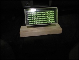
Mini--BMS
All 100 Cells At Equalization Voltage-indicated by both green and red LEDs on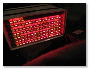
In August, I replaced the coolant pump and revised the software for the NGS2 so it no longer corrupts the SD card. In September, I repaired the blend door motor. Between April and September, we put 8,106 miles on the odometer.
In October I replaced the oil pump for the electric motor. From October 1 through December 2, we added another 2,200 miles to the odometer. We are still getting a range of 80 miles but sadly, winter is nearly here. It sure was nice to pass by the gas stations all summer long but now the truck is going in to storage for a long winter's nap